Search and Rescue missions with Multi-agent surface vehicles
Introduction
The problem of search and rescue in Naval context is present since the early days of Coast Guard(1790s). In the modern day, while most of the processes are automated, search using special geometric patterns still require human intervention from way-point selection to tracking of the pattern. While many people have implemented trajectory tracking controllers for Ship autopilots, the problem of search remains a novel one. In search problems the point of search wanders with the waves of the water body unlike the fixed GPS way-point for ship autopilot. Thus, we see resemblance in the most nascent search operation with Leader follower topology in multi-agent systems. Thus, using the present tools in Multi-agent systems(MAS)
The multi-agent scheme is extremely useful for Surface vehicles due to their slow speeds of operation. By using multiple agents we can surely speedup these processes of search. Keeping this as the basic theme for the project we try to develop a multi-agent equivalent of Victor sierra search which is used by US and Canadian coast guards.
Victor Sierra Search
Victor sierra search
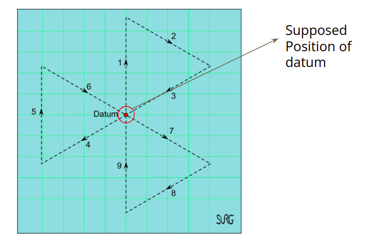
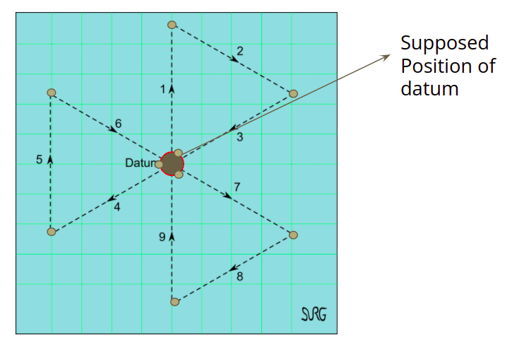
Modified victor sierra search places 9 agents at the edges of the desired motion points. In the setup the agents essentially cover 1/9 of the path as compared to a single agent at the same speed essentially. Due to this reason the design and implementation of this system will greatly help in speeding up the search process. The location of agents is shown in Fig. 2.
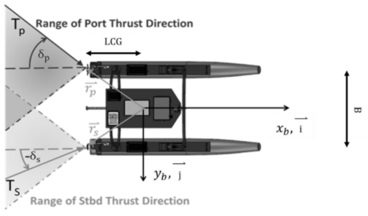
Mathematical Modelling of USV
The mathematical model for the USV can be given as:
\(\dot\eta = J(\eta) v\) \(M\dot v + C(v)v + D(v)v = \tau + \tau_w\)
The first equation comes from the kinematics of the system, the second follows from kinetics of the system. Where \(\eta = [x,y,\phi]; v = [u,v,\omega]\), M is the mass matrix, C is the coriolis force matrix, D is the drag matrix. The individual terms for these are given as:
\[M = M_{RB} + M_{AM} = \begin{bmatrix} m - X_{\dot u} && 0 && 0 \\ 0 && m - Y_{\dot v} && 0 \\ 0 && 0 && I_z - N_{\dot r} \end{bmatrix}\] \[C_{1}(v) = \begin{bmatrix} 0 && 0 && -(m-y_{\dot v})v \\ 0 && 0 && (m-X_{\dot u})u \\ (m-Y_{\dot v})v && -(m - X_{\dot u})u && 0 \end{bmatrix}\] \[D_{1} = \\ \begin{bmatrix} X_{u} && 0 && 0 \\ 0 && Y_{v} && 0 \\ 0 && 0 && N_r \end{bmatrix}\]While, this model helps in establishing mathematical rigor in the control design of a non-linear trajectory tracking controller. We use a non-linear switching PID controller for simplicity, and
Mission and Controller Design
The mission design process can be broken down into three quanta:
- Achieving formation using consensus control.
- Following leader trajectory using trajectory tracking control.
- Conducting search by waypoint following(essentially trajectory tracking for a single point).
On the basis of division of the mission the controller can be visualised as in Fig. 4.

- Multi-agent controller: Takes position of all agents into account to generate a reference position which the specific vehicle should follow. This controller can be further broken down into:
- Consensus controller for formation control.
- Leader follower setup to drive reference points towards the datum point.
- Trajectory Tracking controller: This controller is responsible for the orientation and velocity control of the rigid body dynamics of USV.
- Low level controller: This is generally a PID controller used for actuator control in the present case the platform under simulation implements the PID for actuators.
Prior to discussing lower level controller design there are some insights form the proof of GAS for our dynamics in a trajectory tracking case:
- There is an evident circling problem due to under-actuation along sway present in this system.
- The design on nonlinear control law to reallocate some actuation along the sway direction.
- Design sway agnostic controller.
Keeping this in mind we design a PD controller for surge speed and yaw rate. These controllers take input as yaw error, the reason behind doing this is keep the surge speed agnostic of yaw error. If yaw error is large the vehicle should slow down and try to turn and if error is low we should speed up and quickly track points. This nonlinear mapping is given as: \(u(\phi_e) = 1 - \frac{1}{1+3e^{-0.6|\phi_e|}}\)
The desired yaw angle is given by:
\[\phi_{des} = tan^{-1}(\frac{y_{way} - y_{USV}}{x_{way} - x_{USV}}) - \phi_{USV}\]The controller topology is given as:
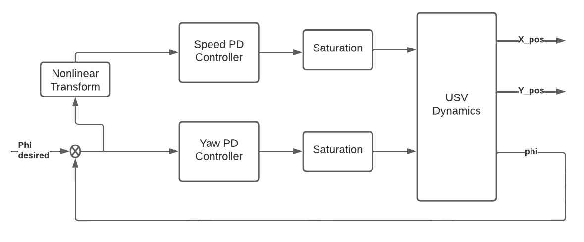
Along with this we apply a control allocation technique(differential thrusters) which is:
- If yaw command is governing towards right:
- Turn on the right thruster and rudder.
- else Turn on the left thruster and rudder.
- If yaw command is small turn on both thrusters for maximum surge.
This can be seen as a switching controller and some analysis can be done by formulating it as the same, another method to make this controller more aggresive is to run the 2nd thruster in an opposite fashion, thus creating more force for turning, however for the USV-16 the motor does not provide much rotation speed in the reverse direction thus, the method is not very effective, some other points that need to be considered before making the scheme more aggresive are:
- Study on oscillations induced due to static and dynamic waves, this would result in slow turning.
- Study on the effect of reverse thrust on the body as the actuator has to drive half of the rigid body.
Based on the analysis of this a control allocation scheme can be formulated. Generally control allocation problem is formulated as an optimisation problem with objective of minimum deviation from setpoint, constraints formulated in terms of actuator constraints with outputs as proportional factors alloted to each actuator. More can be read about control allocation here
For n agents forming an information sharing graph with $X = [x,y]$ the consensus algorithm that helps in attaining the formation as:
\[\dot X_{i} = \sum_{j = 1...N} (X_i - X_j) - \zeta_i - \zeta_j\]Where, \(\zeta_i\) and \(\zeta_j\) are coordinates that the agents desire to achieve that need to be achieved. There is an underlying assumption in consensus is a fully connected graph over the agents. To put this to test generally network simulators like netsim are used however, presently we assume all localisation information is available to all agents instantaneously from the simulator.
The part of the controller used to drive this consensus to the datum point is formulated as a leader follower setup where the leader dynamics govern the movement of the followers and the leader dynamics is given as:
\[\dot x = u*cos(\phi)\] \[\dot y = u*sin(\phi)\] \[u = constant\] \[\phi = tan^{-1}\frac{y_{waypoint} - y}{x_{waypoint} - x}\]Please note that this dynamics is capable of smooth turns thus same is possible for follower agents unlike naive Line of Sight tracking methods.
Results
After conducting multiple experiments with the system and the simulator we present results for openloop response in presence of disturbance, closed loop trajectory tracking performance of the switching controller, Victor sierra formation using consensus and leader follower setup to drive consensus to the goal.
Open Loop results
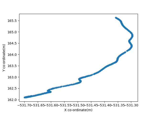
- Case 1: Max thrust to both the thrusters
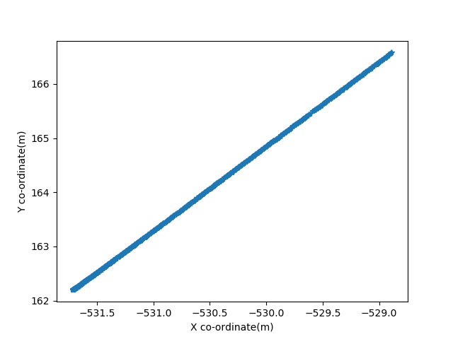
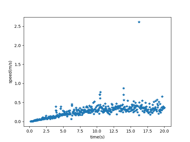
The overall behaviour suggests that the speed eventually becomes contant for a constant thrust,and the values are small even for max thrust, implying the slow system, this will affect turns as well.
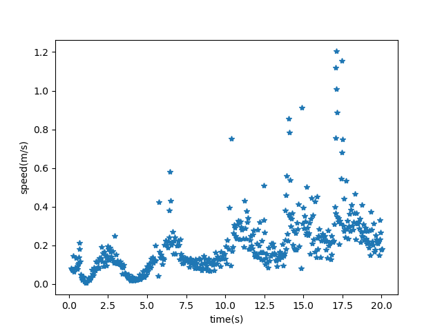
- Next, we try the same with left thruster and left rudder, giving them full throttle and some actuation angle respectively.
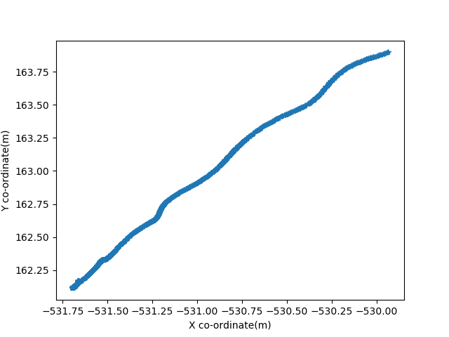
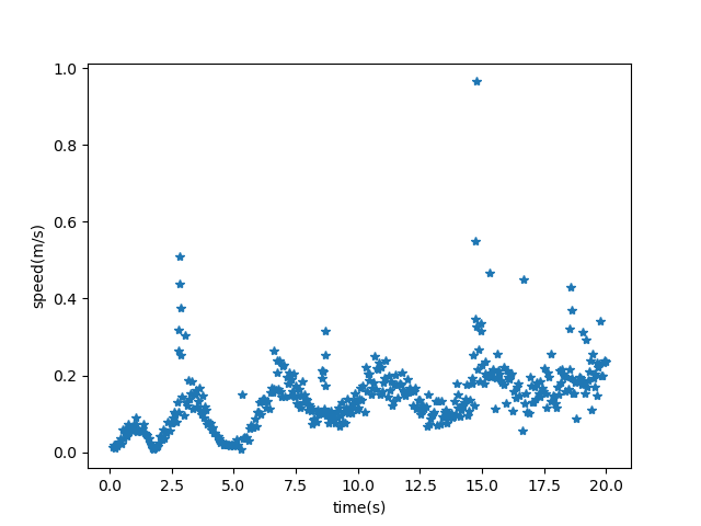
In this case we see that there is an oscillatory behaviour in the speed and that is because of the waves present in the sea that rock the vehicle about a crest and a trough while motion takes place in a rotatory fashion. This indicates coupling between the surge, sway, yaw, pitch and roll. Thus the system requires 6 DOF control for perfect tracking however for out purposes we stick to singular tracking. Similar results can be drawn from right thruster activations.
Closed Loop Results
To test the controller designed for trajectory tracking we perform two tests,
- U turn Test: Tests the overshoot of the yaw controller and the effectiveness of control allocation.
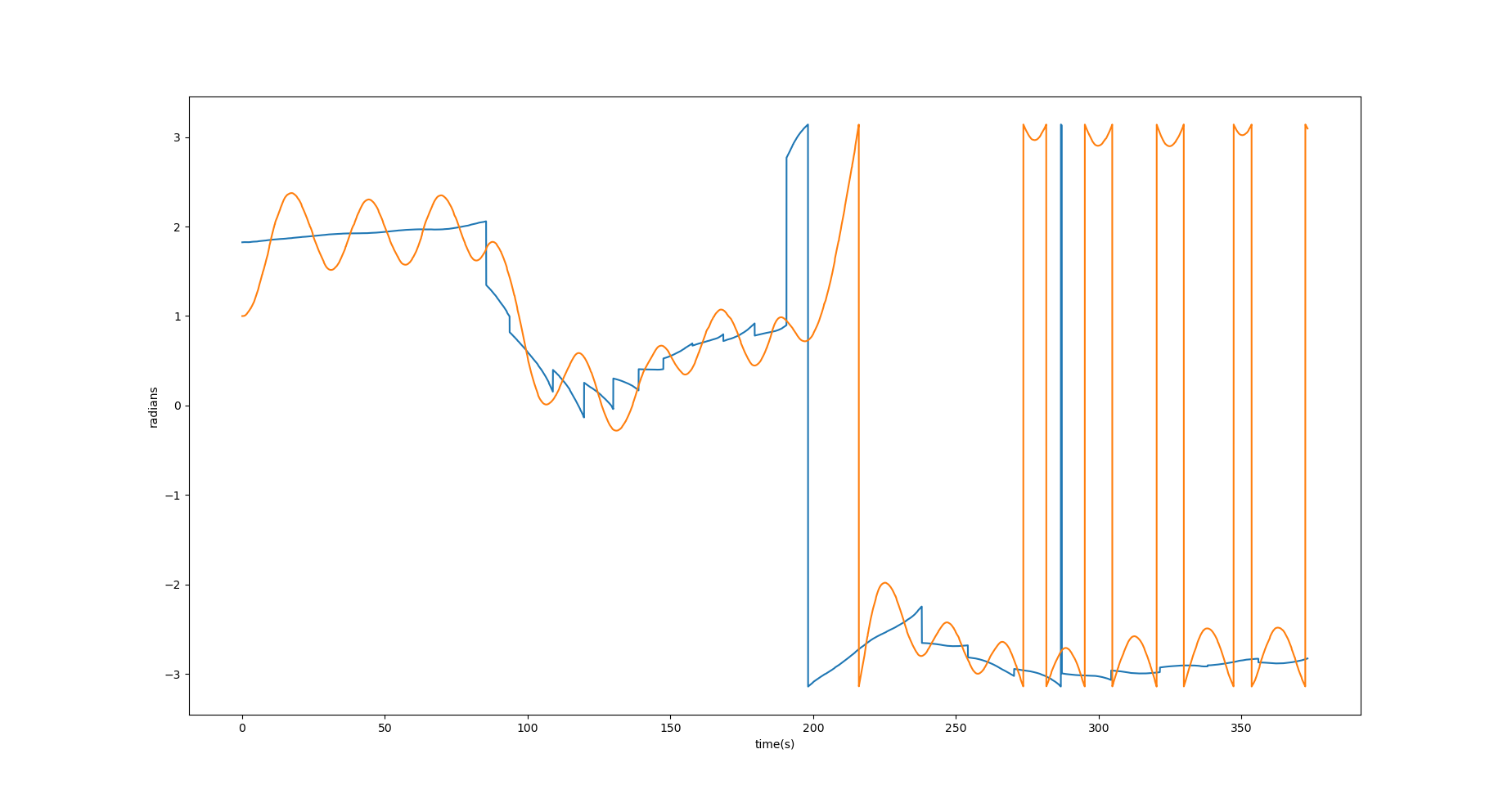
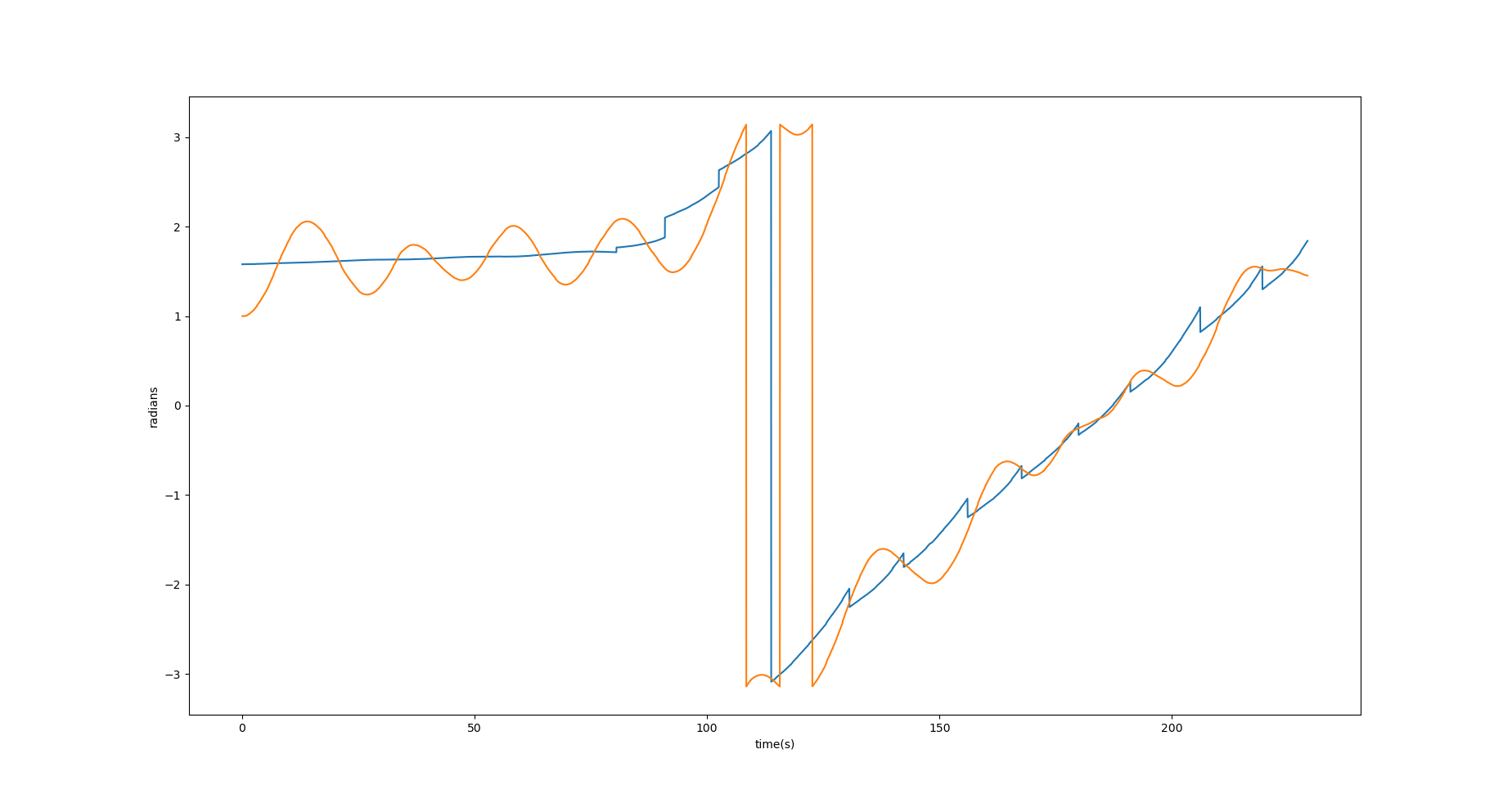
- Circular Test: Tests the overall response of the system. The results can be formalised as:
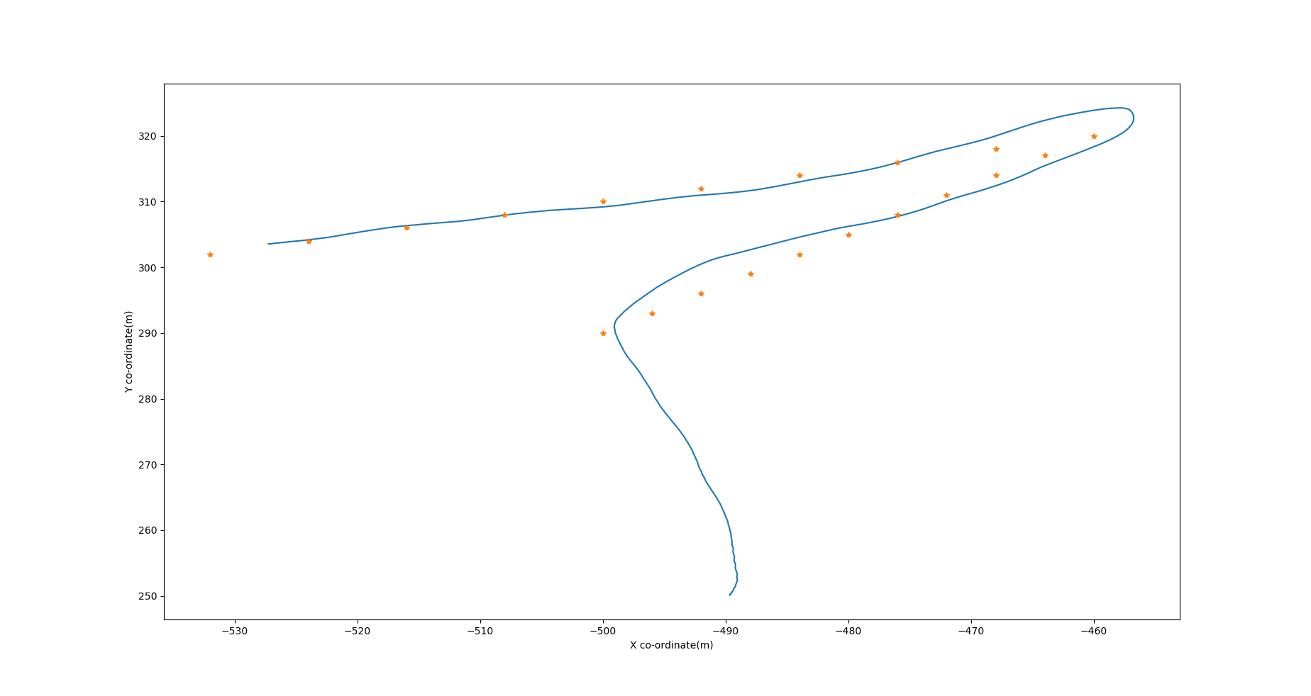
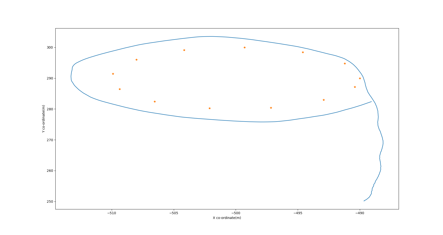
- U turn Test: In figure Fig. 9 we see small overshoot and overall drift of less than 3 m at the sharpest turn. There are some oscillations in the yaw values but could be tuned using iterative runs.
- Circular Test: In figures Fig. 10 there is some drift but less than 2m and chattering around the values \(\pi\), \(-\pi\).
Formation control
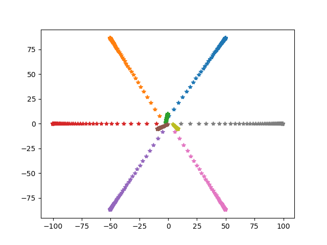
Next the victor sierra pattern can be formulated using formation control algorithm, and Leader follower based formation guidance, the coordinates are those of gazebo.
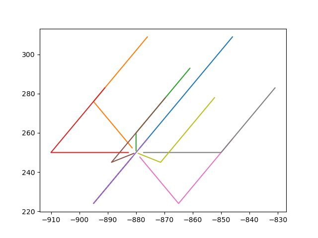
Next when we try to put these formulations together as in Fig. 4. we run into problem of inter-agent collisions, which were out of scope and I am currently trying to comeup with solutions for the same, there are multiple centralised algorithms available however none are realtime, generally scheduling based approaches are used however this is not feasible. Since, our system is slower we have some room to play around with scheduling however in tight spaces and with faster systems this approach maynot work, and I’m still looking into it.
Here’s a video of inter-agent collision problem. The github repository can be found under the repository tab of my website.