openarm_control: Cascaded Joint Control for a Bimanual Manipulator in MuJoCo
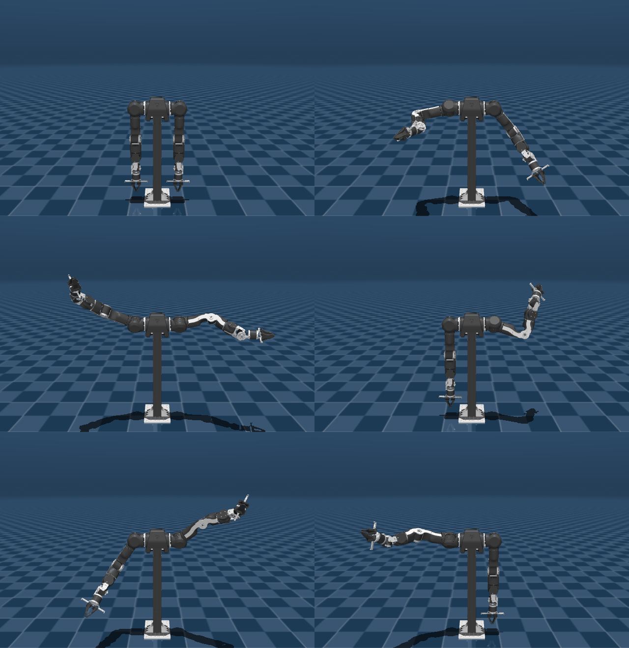
openarm_control is cascaded
joint-space control for the OpenArm v1 bimanual manipulator in MuJoCo: a
position→velocity→torque loop with model-based gravity compensation, plus an
observer/plotter layer for control-signal analysis.
Seven degrees of freedom per arm, torque-level actuation. The same gravity model serves both the simulation path and a CAN hardware path.
Concepts used
Everything this project leans on, in one place:
Control
- Cascaded (nested-loop) control — an outer position loop generating a velocity setpoint for an inner velocity loop generating torque. The inner loop must be substantially faster than the outer or the cascade degrades into a limit cycle, which is exactly what happened on one joint here.
-
PID with trapezoidal integration —
I += (e[k] + e[k-1]) · dt/2, with the accumulator holding raw error and the gain applied only at the output. - Integrator anti-windup by back-calculation — the integral term is clamped to the headroom left between the non-integral terms and the output limit, and the accumulator is recomputed from the clamped value so a saturated output cannot keep charging it.
- Feedforward control — gravity torque and reference velocity are added directly to the loop output rather than being left for feedback to discover.
-
Derivative kick and derivative conditioning — D on velocity error is
(e[k] − e[k-1])/dt, which atdt = 1e-3is a 1000× amplifier on an already differentiated signal; unusable without a low-pass. D on position error is well conditioned by comparison. - Actuator saturation — a step setpoint pins the actuators at their torque limit regardless of gains; no amount of tuning fixes a reference the plant cannot follow.
- Limit cycle vs. divergence — a bounded oscillation whose amplitude is non-monotonic in observation time, distinct from an unbounded one.
Dynamics and simulation
-
Model-based gravity compensation — MuJoCo’s
qfrc_biasevaluated withqvel = 0, so the bias term reduces to pure gravity with no Coriolis or centrifugal contribution. -
Joint-space inertia and effective inertia — measured here by applying a
unit torque and reading the resulting acceleration, with the gravity-only
baseline subtracted:
M_eff = 1 / (a_torque − a_free). -
Inertia-scaled gain selection — for a velocity loop on
M q̈ = τ, a proportional gain gives a first-order response with time constantM/kp, so choosing a target closed-looptau_vfixeskp = M_eff / tau_vper joint. -
Numerical stiffness and implicit integration — Euler integration at high
kpamplifies joint stiffness into spurious oscillation; MuJoCo’sIMPLICITFASTvelocity integrator adds implicit damping that keeps stiff joints stable without detuning the controller. - Simulation state hygiene — a solver that borrows the live state buffer can silently destroy the thing it is measuring.
- Determinism — bounding a run by wall-clock time makes simulated coverage a function of machine speed; bounding it by simulated time does not.
Trajectory generation
- Time-synchronised trapezoidal velocity profiles — accelerate, cruise, decelerate, with the longest-travel joint setting the total duration and every other joint’s cruise velocity solved so all joints arrive together.
- Triangular fallback — when the travel is too short to reach cruise velocity, the profile degenerates to accelerate-then-decelerate.
- Velocity feedforward from the profile — the profile’s derivative is fed straight into the inner loop, so feedback only has to correct the residual.
Kinematics and hardware
- Mirrored joint ranges on a bimanual platform — the two arms share ranges on joints 3–7 but have negated ranges on joints 1–2, so a pose legal on one arm is not automatically legal on the other.
- CAN bus / MIT-mode torque control for the physical actuators (DM8009, DM4340, DM4310).
Control architecture
Two nested PID loops. The outer loop converts position error into a velocity setpoint; the inner loop converts velocity error into a joint torque, with model-computed gravity torques injected as feedforward.
              ┌───────────────────────┐
   q_ref ───► │  Position PID         │ ──► q̇_cmd ──┐
        ▲     │  kp, ki, kd           │             │
        │     └───────────────────────┘             ▼
        │                                          (+) ◄── q̇_ref
        │                                           │
        │                            ┌──────────────┴──────────┐
        │                            │  Velocity PID           │
        │                     q̇_fb ─►│  + τ_gravity (feedfwd)  │ ──► τ_cmd
        │                            └─────────────────────────┘
        │                                           │
        │                                           ▼
        │                              ┌─────────────────────────┐
        └───────── q_fb ───────────────┤  MuJoCo plant           │
                   q̇_fb ───────────────┤  mj_step, IMPLICITFAST  │
                                       └─────────────────────────┘
                                                    │
                                                    ▼
                                          Observer ──► SignalPlotter
Gravity compensation. Torques come from MuJoCo’s qfrc_bias, evaluated at
the current configuration with qvel forced to zero — so the bias term reduces
to pure gravity with no Coriolis or centrifugal contribution. It is computed
against the same MJCF that drives the plant, which makes it exact in simulation
and a model-accuracy question on hardware.
Solver settings. The simulation forces mjINT_IMPLICITFAST with a small
timestep. Euler integration at high kp amplifies joint stiffness and produces
spurious oscillation; the implicit velocity integrator adds implicit damping
that keeps stiff joints stable without detuning the controller.
Repository layout
| Path | Purpose |
|---|---|
scripts/mujoco_sim.py |
Simulation driver: model loading, control loop, headless go_to_motor_angles, viewer replay, CLI |
scripts/controller_impl.py |
PID_Controller dataclass, ControllerData state, FF_Controllers.FF_PID_controller with anti-windup |
scripts/gravity_compensation.py |
GravityCompensationSim (MuJoCo) and GravityCompensation (CAN hardware) |
scripts/trajectory.py |
TrapezoidalProfile — time-synchronised joint-space reference generation |
scripts/observer.py |
Time-series recorder for reference/feedback/torque; .npz save and load |
scripts/plotter.py |
SignalPlotter — per-joint and per-signal figures with error traces |
scripts/config/sim_config.yaml |
Gains and output limits for both loops |
models/openarm_mujoco/ |
Submodule — enactic/openarm_mujoco MJCF |
modules/ruckig/ |
Submodule — pantor/ruckig, not yet wired in |
Torque limits reflect the physical actuators: DM8009 on joints 1–2, DM4340 on joints 3–4, DM4310 on joints 5–7.
Running
git clone --recurse-submodules https://github.com/dt1729/openarm_control.git
cd openarm_control
pip install mujoco numpy pyyaml matplotlib

cd scripts
python mujoco_sim.py                         # left arm to a fixed pose, then replay and plot
python mujoco_sim.py --arm_side right_arm    # choose an arm
python mujoco_sim.py --no-replay             # skip the 3D replay
python mujoco_sim.py --log-level DEBUG       # full control-loop trace
Programmatically:
from mujoco_sim import MuJoCoSimulation
import numpy as np

sim = MuJoCoSimulation(model_path=..., config_path=..., arm_side="left_arm")
sim.go_to_motor_angles(np.array([1.0, -2.0, 0.5, 0.5, 1.0, -0.4, 0.4]), timeout=30.0)

sim.save_data("run.npz")          # persist the trace
sim.visualize(save_dir="plots")   # write figures
sim.replay_in_viewer(playback_speed=2.0)
Analysis output
All figures below are one 12 s step of the left arm to
[1.0, -2.0, 0.5, 0.5, 1.0, -0.4, 0.4] rad.

The trapezoidal profile is visible directly in the top panel: a 0.5 s settle hold, then every joint ramps and arrives together at ~2.9 s regardless of how far it had to travel — that is the time-synchronisation. Joint 2 covers 2.0 rad and joint 6 covers 0.4 rad, and both finish at the same instant.
The bottom panel is the one that matters. Tracking error stays inside ±0.07 rad through the whole move and decays to under 0.002 rad. The residual wobble between 4 s and 10 s is the last of the settle, not a limit cycle — it decreases monotonically.

Useful when a single joint misbehaves: this is the view that isolated joint 5’s limit cycle to its velocity loop rather than anything global.


Torque stays well inside the actuator limits (−9.0 to +2.7 Nm against a ±40 Nm bound on joint 1), which is what gravity feedforward buys — the loops only have to supply the dynamics, not hold the arm up.
Traces persist to .npz through Observer.save() and reload with
Observer.load(), so tuning runs can be compared offline without re-simulating.
Hardware path
GravityCompensation targets the physical arm through openarm_can: it
initialises the seven motors with their type and send/receive CAN IDs, enables
them, then loops reading joint positions, computing gravity torques from the
MuJoCo model, and issuing MIT-mode torque commands. The import is currently
commented out, so this path is inactive until openarm_can is installed.
Defects found and fixed
Recorded rather than hidden: the current gains depend on these fixes, so anyone re-tuning needs the history.
-
Gravity compensation corrupted the simulation state. (dominant)
GravityCompensationSim.compute_gravity_torquesreceived the liveMjDataand executedself.data.qvel[:] = 0to isolate gravity from the Coriolis terms inqfrc_bias— erasing the arm’s velocity on every control step, immediately beforemj_step. The solve now runs on a private scratch buffer. -
dtmismatch. The config declareddt: 0.1while the code forcedtimestep = 1e-4— a 1000x discrepancy in every integral and derivative term. The timestep now comes from the config, and the controller uses it. - Unit mismatch on the outer loop. The position controller emits a velocity setpoint but was clamped to joint angle limits in radians. Its limits are now joint velocity limits in rad/s.
-
No trajectory generation.
go_to_motor_anglesapplied the target as a step, which saturates the actuators regardless of tuning. Moves are now driven by a time-synchronised trapezoidal profile (trajectory.py) whose velocity feeds the previously-unusedvel_state._reffeedforward input. This change alone took saturation from 95% to 14%.
Validation
Step to [1.0, -2.0, 0.5, 0.5, 1.0, -0.4, 0.4] rad on the left arm:
| Before | After | |
|---|---|---|
| Max final joint error | 1.81 rad | 0.000 rad |
| Torque saturation | 88% of run | 0% |
| Residual velocity at rest | 0.65 rad/s | 0.000 rad/s |
| Peak commanded torque | ±40 Nm (at limit) | −9.0 … +2.7 Nm |
Gain sizing
Measured effective joint inertia spans 446x from shoulder to wrist
(0.461 down to 0.0010 kg m²), so no uniform gain profile can be stable across
all seven joints. autogain.py measures inertia by applying a unit torque and
reading the resulting acceleration, then sets kp = M_eff / tau_v with
tau_v = 0.02 s, and ki = kp / 0.2.
Joint 5 is a hand-tuned exception. The inertia rule gave it kp = 0.0518,
which left its inner loop too slow to track its own velocity setpoint: it limit
cycled with a ~3–4 s period while the other six settled exactly. Raising the
velocity-loop kp 30× and cutting ki to 0.3× — the integral was driving the
wind-up — plus position kp 3.33 → 10 took settling from never to 3.0 s and
ripple from 0.283 rad to 0.00057 rad. Adding position-loop D changed the result
by 3%, so it stayed at zero: once the inner loop was fast enough, there was no
lag left for derivative action to anticipate.
Roadmap
- Swap the trapezoidal profile for the
ruckigsubmodule (jerk-limited, online) - Re-enable and validate the
openarm_canhardware path - Cartesian-space control layered on the existing joint loop
- Multi-waypoint sequencing, so moves can be staged rather than fully overlapped
References
- enactic/openarm_mujoco — MJCF model
- pantor/ruckig — jerk-limited trajectory generation
-
MuJoCo documentation —
qfrc_bias, integrator selection
Code at github.com/dt1729/openarm_control.